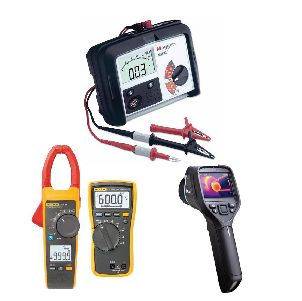
Electrical testing equipment is the backbone of safe, reliable, and compliant electrical work. From verifying the integrity of a single circuit to commissioning an entire industrial facility, the right instruments determine whether diagnostics are accurate, maintenance is proactive, and hazards are eliminated before they become failures. This guide examines the primary categories of electrical testing equipment, their core functions, and the applications where each delivers the most value.
Why Electrical Testing Equipment Matters
Electrical systems degrade silently. Insulation weakens, connections loosen, and protective devices drift out of calibration—often without any visible warning. Testing equipment converts these invisible risks into measurable data, enabling technicians to make informed decisions about repair, replacement, and maintenance scheduling. Beyond safety, disciplined testing supports regulatory compliance, reduces downtime, and extends the service life of expensive assets.
Voltage and Continuity Testers
These are the most fundamental tools in any electrician’s kit, used to confirm the presence or absence of voltage and to verify circuit paths.
- Non-contact voltage testers detect energized conductors without physical contact, making them ideal for quick safety checks before work begins.
- Two-pole voltage testers provide direct measurement across conductors and are essential for lockout/tagout verification.
- Continuity testers confirm that a circuit is complete, supporting troubleshooting of open connections and faulty wiring.
These instruments are used daily in residential, commercial, and industrial settings for pre-work safety verification and basic fault isolation.
Multimeters
The multimeter is the workhorse of electrical diagnostics, combining multiple measurement functions in a single handheld device. Modern digital multimeters (DMMs) typically measure voltage, current, resistance, capacitance, and frequency, with advanced models adding temperature, duty cycle, and data logging.
Key Applications
- Verifying supply voltage at outlets, panels, and equipment terminals
- Measuring current draw to identify overloaded circuits or failing motors
- Checking resistance to locate opens, shorts, and degraded connections
- Testing components such as fuses, switches, and diodes
Technicians select multimeters based on CAT safety ratings, accuracy specifications, and the measurement range required by the task.
Clamp Meters
Clamp meters measure current without breaking the circuit, using a jaw that surrounds the conductor and senses the magnetic field produced by current flow. This makes them indispensable for live measurements where disconnection is impractical or unsafe.
- AC clamp meters support load studies, panel balancing, and motor current analysis.
- AC/DC clamp meters extend capability to battery systems, solar installations, and DC drives.
- Leakage clamp meters detect small residual currents that indicate insulation faults or ground leakage.
Clamp meters are widely used in preventive maintenance programs to trend current draw and flag anomalies before equipment fails.
Insulation Resistance Testers
Insulation resistance testers, often called megohmmeters, apply a high DC voltage to assess the condition of insulation in cables, motors, transformers, and switchgear. Declining insulation resistance is one of the earliest indicators of impending failure.
| Spot test | 500 V – 1,000 V | Quick condition check on low-voltage equipment |
| Step voltage test | Up to 5,000 V | Detecting moisture and contamination in insulation |
| Polarization index | 500 V – 1,000 V | Assessing insulation aging over a 10-minute test |
Regular insulation testing supports predictive maintenance and is a standard requirement for motor and cable commissioning.
Earth Resistance Testers
Proper grounding is foundational to electrical safety, and earth resistance testers verify that grounding systems meet design and code requirements. These instruments measure the resistance between a grounding electrode and the surrounding earth using methods such as fall-of-potential, clamp-on, and stakeless testing.
- Commissioning new grounding systems
- Periodic verification of substation and facility grounds
- Investigating equipment damage caused by poor grounding
Loop and RCD/GFCI Testers
Loop testers measure fault loop impedance to confirm that protective devices will trip quickly enough under fault conditions. RCD/GFCI testers verify the correct operation and trip time of residual current devices, which protect people from electric shock.
These tests are mandatory in many jurisdictions during installation and periodic inspection, and they provide documented evidence of protective device performance.
Power Quality Analyzers
Power quality analyzers capture and record detailed electrical parameters over time, including voltage sags and swells, harmonics, transients, flicker, and power factor. They are essential when equipment misbehaves in ways that basic meters cannot explain.
Common Use Cases
Thermal Imaging Cameras
Though not purely electrical instruments, thermal imagers are a cornerstone of electrical inspection. By revealing temperature differences, they expose loose connections, overloaded conductors, and failing components before visible damage occurs. Routine thermal scans of panels and switchgear are a cost-effective preventive maintenance practice.
Choosing the Right Equipment
Selecting electrical testing equipment requires balancing safety ratings, accuracy, durability, and the specific demands of the environment. Key considerations include:
- Safety category ratings appropriate to the voltage and energy level of the system
- Measurement accuracy and resolution matched to the application
- Calibration traceability to maintain compliance and confidence in results
- Data logging and connectivity for trending and documentation
Conclusion
Each category of electrical testing equipment serves a distinct purpose, and mature electrical programs rely on a combination of tools rather than a single instrument. Voltage testers and multimeters handle everyday diagnostics, clamp meters and insulation testers support preventive maintenance, earth and loop testers confirm safety systems, and power quality analyzers and thermal cameras uncover the subtle issues that basic testing misses. Investing in the right equipment—and in the training to use it correctly—is the most direct path to safer systems and fewer unplanned failures.
Leave a Reply